The Alfatross

The Alfatross
The Alfatross in 1965 and 50 years later in 2016

Saturday, November 25, 2017

Hotfooting It (Post # 135)


Wrapped headers on chassis *01909*.
 The Heatshield Products exhaust armor's
inner ceramic fibers layer is capable of
withstanding 1800 degrees F continuously.
Now we're back to the exhaust system, following Post # 129. The Alfatross has a hot engine. No, really, I mean HOT! And the exhaust gasses are the hottest part.  Alfa engineers knew this, so 1308 SS engines came from the factory with aluminum and asbestos heat shields protecting the starter, generator, and part of the steering column from the intense heat radiating off the headers.  A dedicated aluminum scoop and shroud ventilated the entire exhaust side of the engine when in motion, but was of little help otherwise. We need to get those hot gasses away from the car as fast as possible while at the same time keeping the decibels down to a civilized level. Alfa engineers put the first of three pairs of mufflers or resonators right under the driver's seat. At this point in the system the gasses are still at a few hundred degrees F. This might seem like a dumb thing to do, but if you look around under the chassis there really isn't any other place to put it, given that the chassis is short and you still need to find space for two more muffler pairs. 
The corrugated metallic outer layer keeps the
inner layer together and allows it to be shaped.

We discovered this "engineering compromise" during the 2016 Arizona Concours d'Elegance. Positioning the cars on the field in the wee hours took a long time, with a lot of stopping, idling, and waiting.  Even though the pre-dawn January morning was quite chilly the cabin became uncomfortably warm very quickly.  Fellow 1900C SSZ owner David Smith experienced the same phenomenon while preparing his car (*01947*) for Pebble Beach this year. During road testing the floorboard got so hot it started to melt his shoes! The only viable solution is to add more insulation between the first pair of mufflers and the floor under the driver's seat.


The Heatshield Products "Exhaust Armor" installed on 
top of the insulation previously fixed to the bellypan creates 
a good two cm total insulation between the exhaust system
 and the floorboard directly under the driver's seat. 
The third muffler pair hides in a recess in
the bodywork with no more than half an 

inch of clearance on either side.  

Trial fitting the Quicksilver exhaust system in preparation for tack-welding.  Altogether there are 10 joins, 2 hanger tabs, and a brace to weld.

Now that The Alfatross' new Quicksilver exhaust system is welded up and almost ready for installation, it's time to beef up the insulation in a discreet manner that does not detract from its originality. There is no question that insulation materials and technology available today do their job quite well, and some 1900 owners have gone so far as to wrap their headers, but some authorities think this practice may be damaging to the headers themselves. In any case use of header wrap for The Alfatross would be an inappropriate anachronism. On the other hand, replacing the traditional asbestos insulation attached to the bellypan beneath the driver's seat with modern materials is easy to do and should make a big difference without even being visible. 

Another place where the exhaust system could stand additional insulation to keep it from damaging the body paint is the muffler recess in the trunk area where the last pair of mufflers reside. On Zagato bodied SS cars like The Alfatross this space is only about 7 inches wide, leaving about half an inch of space on either side of the twin mufflers--too close for comfort!  


The Lava Shield mat material looks like carbon fiber and
is only 0.008 thick, but is said to reduce radiant heat by up
to 80%.  

After some online research I ordered two different kinds of insulation for the two applications, both manufactured by Heatshield Products (https://www.heatshieldproducts.com/): "Exhaust Armor" for the area under the driver's seat and "Lava Shield" for the last pair of mufflers in the recess. "Exhaust Armor" is a mostly fibrous ceramic material 0.50 inch thick bonded to a dimpled metallic sheet said to be able to resist 1,800 degrees F continuously, while reducing radiant heat by 60%. "Lava Shield" is a completely different material ("made of crushed volcanic rock" according to the manufacturer).  It comes in the form of a self-adhesive mat only 0.008 inch thick but capable of reducing radiant heat by 80%.

At this writing the Quicksilver exhaust system is back on the workbench following a test fitting to make sure everything is still in alignment after welding. The next step is prepping it for coating with the same high-temperature flat black paint I used on the first system.  I won't know how effective the heat shields are until after the whole system is back on and the engine fired up. One thing I can say for sure is this better be the last time anything having to do with the exhaust system needs attention--I'm tired of living under a car!


Thursday, October 19, 2017

What Does The Alfatross Have in Common with Washington DC? (Post # 134)


The Alfatross is marking its territory.  How do you
determine the severity of a leak from its puddles?

They both have leaks!  


Engine oil leak fluorescing under ultraviolet light showing that the 
leak is between the pan and the sump.
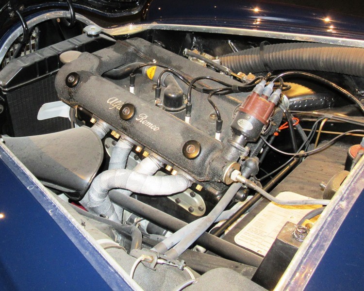
The Alfatross has several circulatory systems for its various fluids: coolant that circulates between the radiator, engine, and heater; oil circulating throughout the engine from the oil pan to the oil pump to the cylinder heads, camshafts, crankshaft, and piston rings; fuel that has to move from the gas tank to the electric fuel pump to the mechanical fuel pump to the carburetors; brake fluid that moves from the reservoir to the master cylinder to the wheel cylinders and part way back; steering gear fluid inside the steering box; hypoid gear oil inside the differential; and even another type of oil splashing around inside the transmission.  

It seems that all those different fluids just can't wait to escape and are looking for opportunities at every turn. It isn't easy to keep them in captivity. Because they are relentlessly stored, released, heated, cooled, compressed, decompressed and recycled while doing their jobs, they have to pass through tubes, chambers, reservoirs, pumps, valves, and sumps made from different materials with different expansion and contraction coefficients--all grudgingly held together with different types of seals and gaskets.  It's not an easy life.
Minor leak from a crack at the engine oil temperature port
in the back of the sump.

We tend to forget this because automotive engineers have virtually eliminated engine oil leaks in modern cars, but things were different when The Alfatross was born 62 years ago.  Oil and fluid leaks were more or less expected and not cause for alarm.  I was reminded of this recently during correspondence with members of the "Alfa 1900 Brain Trust".  After determining that The Alfatross has an engine oil leak somewhere between the pressed steel oil pan and the sump, as well as a crack just below the oil temperature sensor port in the sump, I sent out a plaintive query asking what could be done to fix them short of pulling the engine.  The responses were as bleak as they were historically enlightening:

Joost Gompels (gallows humor): My car leaked oil. I thought it was the oil temp sensor at the back of the oil pan and the gear box from a bad shaft seal as it got less as the oil level fell. Possibly hairline cracks in the casing.  I found it hard to seal the cam rocker covers because of the locator pins, warpage and overtightening. Thought we all subscribed to the wisecrack that if an Alfa did not leak--it had run out of oil! 

Peter Marshall (look on the bright side): I duuno!  I always thought that the Austin 7 survived well because the chassis accumulated a little oil rather than rust. I have never looked that hard at whether 1900s drip much. 

Giuseppe Maranghi (careful how you treat it!): As all pre-Fiat Alfas have a generous oil pump, both in pressure and quantity, NEVER run at hi revs a cold Alfa engine, otherwise the cold oil, supported by the generous pressure, will find by itself more than one way to "escape" out of the block. Did You all know that Motorway Police Giulia SW had a sort of heating plugs, like those for diesel engines, to keep the engine properly warmed in case of emergency? 
Dan Allen (just cowboy up and fix it!): Steel is more susceptible to vibration cracks especially around fittings and seams. I think anyway.  Also Don, it is very unlikely the engineers design an engine with thought of future R&R [in response to my observation that you can't remove the oil pan and sump without removing the engine].  Generally Alfa liked to put the engine and trans together for installation and most likely would recommend the same if they needed to come out. [meaning that I would have to remove both the engine and the transmission just to seal a leak in the oil pan!]
Joost (Oh those pesky Russians!): One cannot generalize too well. There are many different types of steel and alum alloys. Take an aircraft and a bridge for example. One is aluminum and the other steel almost exclusively yet both flex and vibrate in service not to mention expansion and contraction. Giuseppe may wish to comment on this that Italy after WWII had to import low quality Russian steel while able to manufacture aluminum itself. So it's choice of materials might be governed by other factors. Basically aluminum is a better heat conductor and its bigger mass and the ability to easily cast fins on its outer surfaces lets it dissipate heat from the oil pan better than a steel one.  
Giuseppe ("Stalin", in Russian, means "made with steel"): Well, it's not a comment, it's History, but nobody will find it in Italian books:  When Fiat decided for a joint-venture with Stalin "and company", the payback was not Russian "rubles", but full-of-sulphur (and maybe something else!) Russian steel, hence those 127s, 131s, Lancia Betas, Alfettas, Alfa6s and, above all, Alfasuds, carved like Swiss cheese. Italy, having the biggest communist party in the western block, even supporting Red Brigades, and all big factories in need of steel--Alfa Romeo  included--had to buy Russian one, just to keep the political situation quiet.


Leaks--how much is too much?

  
5 ml of engine oil isn't much!
By modern standards, any leak is too much.  By 1955 standards a small leak is nothing to be concerned about, but at what point should you start to worry?  One slow afternoon I did an admittedly sketchy experiment to figure out how much engine oil The Alfatross is losing over time. Because the drops from the leaks were landing in different places under the car I could not easily measure the volume of leakage, but I could measure the size of the puddles and compare them with surrogate puddles made from precise amounts of oil created elsewhere on the shop floor.  I filled a syringe with 1, 2, and 5 ml amounts of the same kind of oil in the crankcase, squirted them on the floor,  then waited a couple of days to see how much area they spread out to cover.  To my surprise, the three samples spread out and joined up to create a puddle about 9 inches (23 cm) across.  I estimated a puddle that size would represent at least a couple of week's worth of leakage. If The Alfatross' crankcase holds about 8 quarts of oil and there are 946.353 ml in a quart, there are 7,570 ml of oil in a full crankcase.  Assuming a steady rate of leakage of 0.57 ml/day it would take about 1,887.6 weeks, or about 36.3 years to drain the crankcase!


Individual puddles created by 5, 2 and 1 ml
"drips" before spreading out.  Scale is in
cm.
The puddles spread out to form a single
puddle estimated at about 9 inches or 23 cm
across.  Roughly 2 weeks worth of leakage.


So call me obsessive, but that's too much!


Tuesday, September 19, 2017

Small Change Saves Big Bills (Post #133)


This exploded diagram of a 1900 Alfa's rear suspension from the official Alfa Model 1900 Parts Catalog solved a mystery, saved me a lot of trouble, and once again proved that you cannot take too many photos or make too many sketches when you are in the disassembly phase.

I took The Alfatross' rear suspension apart about 25 years ago when I still had not learned that lesson. I bagged all the parts and labeled them but--digital photography being at that time not even a glimmer in anyone's eye--did not have the means to photograph everything in its original location on the car.

When I reassembled the rear suspension about 18 months ago I re-used almost all the original cleaned and restored parts except for the drop stop straps.  The originals were made of some kind of fibrous material that was worn, frayed, tattered, and unsafe so I replaced them with widely available new reproductions that come with neatly cut holes ready to install. 

All I had to do was bolt the straps to the chassis under the big rubber bump stops, wrap them around the axle, and connect the ends. Among the rear suspension parts I had two small steel plates with holes matching the spacing on the straps, but mistakenly assumed [Mistake No. 1: don't assume anything.  Spend the time necessary to think it through.] that the straps were supposed to be secured end-to-end, which would mean that I was really supposed to have four little plates, not just two [Mistake No. 2: The more assumptions you have to make, the more unlikely an explanation is.] So I cut and drilled two steel attachment pieces, each with four holes to fill that function--and thought I was being very resourceful.


The "over-improved" drop stops utilizing
fabricated plates to connect the strap end-
to-end instead of overlapping. The result of
a failure to apply Occam's Razor.


The drop stop clamp plates.  Note the distinctive
ridges along the edges.


The Parts Catalog drawing of the drop stop shows clearly
that the strap ends overlap each other and (not so  clearly)
that they are secured with  two sets of bolts, washers, and
nuts passing through the holes in the straps and clamp

(no. 29). 
While replacing the rear suspension springs in order to lower the ride height I had occasion to look at the exploded diagram in the Parts Catalog again. This time, I noticed the small window in the upper right corner showing all the parts for both the drop- and bump-stops and finally realized that I had the right parts all along, I just wasn't putting them together right!  Not only that, I went to a lot of unnecessary trouble to do it all wrong!

Correcting this seemingly small mistake shortens the strap length and reduces the distance the rear axle can move downward by more than an inch. I am sure the Alfa engineers who designed the suspension system set the drop stop distance where it is for a reason, and allowing the rear axle to move an inch or more downward could cause damage to other components under certain circumstances, so I am relieved to correct this mistake in time.  It also means that the exhaust system can be attached an inch closer to the chassis. 


Correct attachment with strap ends overlapping and held together
with 10 mm bolts passing through the steel clamp plate, straps, washers, and
secured with nuts. 

So now, having removed or detached, replaced or reconnected the fuel pump, fuel lines, brake lines, emergency brake lines, axle supports, drive shaft, rear springs and drop stops in order to get the ride height sorted out . . . I can finally get back to where I was a month ago: attaching the new exhaust system.  

Sunday, September 17, 2017

High Anxiety (Post # 132)

The Alfatross in about 1966.  The ride height is correct
and the tires fill the wheel openings nicely. Pat Braden.
I realize that the thread for The Alfatross' blog right now pertains to fitting the new exhaust system, but in order to continue with that we have to go back to fooling around with the suspension system because the exhaust passes underneath the rear axle. In order to figure out how close to the chassis to fit the exhaust, we have to know the vehicle's ride height and how far the rear axle can drop before being restrained by the "drop stop" straps. So there are two elements in The Alfatross' current rear axle configuration that have to be modified: the springs and how the drop stop straps are connected.


The Alfatross' ride height after fitting reproduction
springs front and rear--are we going off-roading or what?
The fact that the Alfatross' springs made it ride too high, particularly in the rear, was as obvious as it was puzzling. When I disassembled the suspension system 3 years ago I discovered that one of the front springs was broken, but the original rear springs were in perfect condition.  I knew I would have to find or make new front springs but figured I could re-use the rears.

The ride height is much better after using shims to lower
the front suspension and fitting springs re-designed and
manufactured by Hyperco.
I heard that other 1900C SSZ owners were experiencing similar ride height problems. Only later, after David Smith sent me a copy of the Alfa Romeo Model 1900 Parts Catalog, did I discover that there are at least 8 different rear spring types for different Model 1900 variants including 1900C, 1900L, 1900C SS, 1900 ambulance and, finally, 1900 C Super Sprint dalla vettura no. 10,001 Coupe Zagato! Up to that point I thought there were only two spring types, one for regular production Alfas and another for coach-built lighter cars like Zagatos. Photos of The Alfatross from the 1960s show it with the kind of original ride height I am looking for.  With the probability of finding OEM springs being vanishingly small the only alternative was to have new ones designed and manufactured. 

I got in touch with Peter Marshall who supplied me with copies of period technical drawings and specifications for front and rear springs specifically designed for Zagato-bodied 1900s.  Hyperco (http://www.hypercoils.com/) used that information to reproduce the new front and rear springs that I installed before the Arizona Concours d'Elegance in January 2016.  I didn't like the ride height, it was too high, but didn't have the time or energy to rework the entire suspension system until this summer. 

Shimming the front suspension was fairly easy and lowered the front ride height without modifying the springs, but the only way to lower the rear suspension was to manufacture "new" new springs.  I have no idea how to make a spring, but I now know that it takes a lot of data-gathering and analysis before any actual spring steel gets bent into a spiral--and you won't know if you got it right until you fit them to the car!  Hyperco engineer Mark Campbell used the weights and dimensions I sent him to fabricate a pair of "new" new rear springs.  Now that the old exhaust system is off the car it was time to install them. 

The process of separating the rear axle from the car so that the old springs could be removed and the new ones installed turned out to be a lot easier than the first two times I did it, which surprised me because this time I did it by myself.  I guess it was a good example of "practice makes perfect".  I hope I never have to do it again as long as I live, but this time I wrote down the 14 steps it takes--just in case I do.  After all, I didn't think I would have to do it more than once and it has already been 3 times!
The new Hyperco rear axle spring at left
compared to the taller reproduction spring
fabricated exactly according to Zagato
specifications--but still too tall!


The ride height before installing the new springs.  The top
of the wheel arch is 29 3/8 in. from the bottom of the tire.


After fitting the new new rear springs the ride height is 3
inches lower--just about right!


I think that the ride height in the rear will "settle" further over time. In any case with a full tank of gas, both front seats back in the car and a driver and passenger the height will be lower still.

So now I can get back to finishing the exhaust system, right?  Not so fast! What about those drop stops mentioned in the first paragraph?  Are they too insignificant to mention? No!  They are so important they deserve a post of their own--(Post #131) . . . . 


Friday, August 18, 2017

Quicksilver to the Rescue (Post # 131)

Armed with the "Need to Know",  Dave's MIG welding
setup, and a confident, but misplaced sense of 
"How Hard
 Can It Be?", I finally screwed up the courage to start 
welding.  Let's hope I don't also screw up the exhaust 
system! 
Better late than never . . . . I spent a few days last week teaching myself how to MIG weld, something I should have done years ago but didn't have a sufficiently compelling "need to know" until now. Replacing The Alfatross' exhaust system provided the need and, as luck would have it, Dave Carrell just happened to have a complete MIG welding set he no longer needed. It's amazing what you can learn on U-Tube these days . . . .

The system Jeff Robison and I put on The Alfatross last year was good enough for the car to do well in the 2016 Arizona Concours d'Elegance and Santa Fe Concorso, but I knew it wasn't an exact reproduction of the original. And it sounded a little too loud--OK maybe more than a little--even to my admittedly "insensitive" ears.   
After removing the part of the exhaust system that still
survived, I sketched it and added a few gross measure-
ments.  Note the crossover pipe between the two long
straight sections.  

When I got The Alfatross in 1969 it was already 14 years old and had spent at least half that time in Michigan and Illinois subjected to harsh winters and salted roads. In those days no one expected an exhaust system to last that long, so I wasn't too surprised to discover that The Alfatross' was intact but heavily rusted from the headers to the rear axle . . . where it ended abruptly!  Beyond that the system was entirely missing except for a hanger strap dangling forlornly from the frame.  I concluded that the remaining elements of the system were original and made a simple sketch with measurements. But what about the missing parts? What did they look like?   

I was surprised how complicated the remaining system was with twin pipes running the whole way through at least two sets of mufflers.  The large cavity in the bodywork next to the trunk was obviously for another muffler or resonator, but I couldn't tell if the pipes were supposed to pass over or under the rear axle on the way there.  It took several years to figure that out.
This period photo of one of The Alfatross' siblings shows
that the twin tail pipes are not just straight pipes, but
angle down from inside the body before angling up. 


The official parts catalog is the ultimate
source for establishing what is original!
Note the crossover between the two 

long pipes.


The breakthrough came when I found this illustration in the 1955 Alfa Romeo Model 1900 parts catalog that David Smith sent me.  Not only does it show the complete system including the headers (The Alfatross' original headers were in excellent condition), but also the absolutely essential heat shield located between the first muffler and the driver's seat!  As I was to discover later after I got the car running, that muffler gets really hot!
I also found a page from an in-period catalog offering replacement exhaust system parts.  Back in the day I could have bought a full system including the headers for only 63,500 lira. I have no idea what that  translates to in modern dollar$, but it doesn't sound like a bargain . . . .
As a result of all this I knew what an original exhaust system should look like, but did not want to try to make one from scratch and for years couldn't find a decent reproduction . . . until several months ago when David Smith made me aware that Quicksilver Exhaust Systems, based in England, now makes a very authentic stainless steel system for Alfa 1900C Super Sprint spec cars.  I was delighted to discover that the US distributor for those systems is The Creative Workshop in Dania Beach, FL, an outfit that has already been very generous and supportive of The Alfatross' restoration. I e-mailed proprietor Jason Wenig, ordered the full system, and it arrived about three weeks later. Compare that to the order I placed with AFRA last year. It cost almost the same but took 9 months to manufacture and in the end there wasn't a single piece I could use!
The Quicksilver exhaust system came in 17 pieces running from the headers to the tailpipes and including the clamps and hanger tabs .  The head pipes, straight pipes, and tail pipes had to be shortened considerably to fit the short wheelbase of the Zagato-bodied Alfatross.

So now I am deep into the process of lining all the parts up, supporting them under the car, marking them, cutting off excess length, making sure they fit, positioning the hangers, attaching the header flanges, and tack-welding it all together. It should be finished by next week, but will still need to be coated. It turns out that there are a lot of other things that should be done while the exhaust system is off, including adding additional insulation to the heat shield, removing and testing the brake master cylinder, adding a filter to the fuel line, and installing the new, shorter coil springs on the rear axle. 

The Piston Head Army


Yes, there is still a lot of work ahead.  Problem is, I got distracted by all the things you can do with a MIG welder.  Now I'm looking for excuses to play with it . . . . 

Friday, August 11, 2017

More Brake Mysteries (Post # 130)

Following up the last post about The Alfatross' drum brakes, which was already longer than it should have been, there are still some observations I need to make and a lingering, pestering question I need to pose.  


Drum brakes vs. disc brakes

An historian of automotive history might ask why manufacturers and even racers kept making and using drum brakes long after disc brakes had been invented and proven in battle.  As a person who owns cars with both types of brakes I can say with certainty that discs do a much better job of stopping, and as a mechanic who works on both types I can't understand why drum brakes were ever used on cars in the first place.  After all, the first appearance of disc brakes on a production motor vehicle was in 1902!
The Alfatross' finned aluminum brake drums.  Note the
air scoop attached to the backing plate at left.
The front drums, which are enormous, do most of the
braking and completely fill the space inside the wheel
rims.

The Alfatross was built the same year that modern hydraulic disc brakes began to appear on production European cars such as the Citroen DS, but it took another decade before 4-wheel disc brakes appeared on production cars in the US.  That said, the brakes on The Alfatross exemplify a high degree of refinement of drum brake technology.  All four drums are made of cast and machined aluminum with steel liners, reducing unsprung weight. All drums are finned to increase surface area and improve cooling. The fins on the rear drums are cast parallel to the direction of wheel travel while the front drums are cut diagonally to the direction. Under speed, scoops on the backing plates of the front brakes force air across the fins to further maximize cooling and reduce brake fade. 


Front brake shoes from the Alfa factory
repair manual. Note the two wheel cylinders,
 location of the liners on their shoes, and how
 the liners are attached to their shoes by
rivets.
Inside the drums, the shoes are aluminum, again  to reduce unsprung weight. The front brakes are equipped with two wheel cylinders per wheel to better handle the stronger forces, while only one cylinder is sufficient for the rears. 

One concession to modernity necessary during The Alfatross' restoration was the replacement of its original brake liners with asbestos-free liners chemically bonded to their shoes instead of being riveted as were the originals. 


Right rear brake shoes from the factory
repair manual.  Note the the liners are offset
 on their shoes. 


One of Dan Allen's shoes fitted with the thicker 1/4in
(6.4mm) lining (above) and the thinner 3/16in (4.8mm)
lining more in keeping with the originals.

Rear Brake Liner Mystery

As reported previously, The Alfatross has been plagued by a mysterious problem that rendered the rear brakes ineffectual.  One of the suggested causes was brake shoe linings that were too thin or drums that were too worn. Measuring the inside diameter of the drums revealed they are well within specification, so that eliminated them from suspicion. 

To test the "linings too thin" theory Dan Allen had four of his spare shoes re-lined with thicker material and sent to me. I thought "Now this will surely be the cure!". Much to my dismay, the extra 1/16in of lining prevented the drums from fitting over the shoes! Now we know the thinner linings are not the problem. Not that it matters any more, because at this point I am hopeful that the rear brake problem was solved during the process described in the previous post (# 127)--but I won't know for sure until I put the whole system back together and test it. 
When I unpacked the newly re-shod brake shoes Dan 
Allen sent I noticed that two of them had linings across 
the entire surface of the shoes (upper example) and two 
had linings that only partially covered the shoes. 
Was that intentional or a mistake?

The lingering mystery that no one has been able to solve so far: While fiddling with the shoes Dan sent I noticed that two of the four linings are not applied evenly across the faces of their shoes, but asymmetrically offset a considerable distance more toward one end of the shoe. You can see it clearly in the images above and below. The other two are symmetrical, as one would expect. At first I thought this was some kind of oversight or mistake.  Did the brake shoe re-liner guys run out of material? But then I noticed a similar arrangement in the image of the rear brake shoes in the factory repair manual. The image of the front brake liners shows they are evenly and symmetrically distributed across the face of their shoes but both rear liners are offset.  There must be a reason for this but so far no one has come up with a definitive explanation. 

Definitive explanations, scientific hypotheses, and wildass guesses are herewith invited . . . .


A pair of the new linings seen from one 
end . . .
. . . and seen from the other.  what's
going on?


Tuesday, June 27, 2017

The Blessed "Ah-Ha!" Moment (Post # 129)

The Ah-Ha! Moment. It's what keeps you coming back for more. It even almost compensates for all those hours you spent thinking inside the box. It even almost counteracts the inevitable feelings of inadequacy and block-headedness that burst into technicolor clarity when you realize that if you had just noticed it four hours ago you could have spent those hours more profitably slaying the next mechanical dragon on the seemingly endless list of "to-dos". 

I had one of those today after working for hours and achieving little. Truthfully, I almost gave up. My neighbor Andre wandered in at one point. He has 6 decades of experience working on the whole spectrum of cars and motorcycles--new, old, cheap, expensive, foreign, domestic, stolen, you name it--that came through his shop in New York City. His conclusion was the same as mine: "you haven't properly diagnosed the problem yet.  Don't start messing with it until you know what's wrong!"  And then he left to exercise one of his Porsche 911s leaving me to to figure out why I was assuming something was right when it was really wrong.


The lining on the new shoes (upper) is both different in composition and a lot thicker than the lining on the original shoes.
The original suspicion was that the brake linings on the rear shoes were not sufficiently thick to make strong contact with the drum linings.  Dan Allen came to the rescue (again!) by furnishing shoes with thicker linings that I could use to replace the originals. After installing the new shoes, and with the adjustments contracted to the maximum, it was clear that the linings on the new shoes were too thick to fit inside the drums--aargggh!

So now I was back to refitting the old shoes and linings--and discovering that the shoes no longer fit inside the drums! 

Changing chairs did it. Because my "MaxJax" lift stops at 48 inches, I do a lot of the work under and around The Alfatross sitting on an old roll-around office chair. After frittering away more hours than I am willing to admit trying to figure out why the right rear wheel brake drum stubbornly refused to fit over the newly-installed brake shoes, I changed to a taller chair. Suddenly, from this new perspective, I could see that the shoes were not aligned concentrically with the axle. But what was causing it? It went together before, why not now? I racked my brain to figure out what changed.  The rebuilt wheel cylinders? 

No! Not the recently rebuilt wheel cylinders! The "Ah-Ha" moment occurred when it occurred to me that the two "pistons" in the adjuster mechanism might not be identical--that I might have assumed they were because the difference might not be obvious.  If that were the case, the shoes might be too far apart to fit inside the drums.


The revelation: something is wrong with the brake adjustment mechanism--but what could it be?  The mechanism has only 4 parts: the housing, two "pistons, and a screw.
The housing for the adjustment mechanism, bolted to the
backing plate.  Note the grooves in the housing to receive
the steel tabs at the ends of the brake shoes.

The Alfatross' front brakes are brilliant, but the rear ones have been problematic ever since I first installed them more than a year ago. Drum brakes look simple, and they are--the ones on The Alfatross are an elegant solution to several engineering problems at the same time. Because the brake shoes have to be centered inside their drums, a good drum brake design must let them "float".  


To adjust for wear on the brake shoes,  the
"pistons" are moved apart by turning a
tapered, faceted screw on the back side  of the
 backing plate.  The screw forces the two
"pistons" apart  equally, moving the shoes
equally closer to the brake drums.


I don't know how to describe the shape of the
rear brake adjustment "pistons" so just try to
imagine steel pistons with a perpendicular cut
at one end with an angled slot milled down the
 middle.  At the other end of the "pistons" two
 of them are cut at 45 degrees parallel to the
slots and two are cut at 45 degrees
perpendicular to the slots!  
The Alfatross' rear brake shoes are not "anchored" in any way. The drums themselves are steel where they mate with the shoes, but that thin band is encased in finned cast aluminum to dissipate the heat generated by friction. They also have to be adjustable to compensate for wear, and it was the adjustment mechanism that spoiled my day. I was deceived by its apparent simplicity. To compensate for reduced lining thickness due to wear, the shoes can be moved closer to the drum linings by turning a screw on the backing plate. Inside the adjustment mechanism, the screw has a faceted, tapered point that engages the flat sides of two cleverly-designed pins encapsulated inside a machined steel housing bolted to the backing plate opposite the wheel cylinder.
See what I mean? It's easy to think they are
all alike!

I disassembled the adjustment mechanisms on both rear wheels, extracted the "pistons"--and the "Ah-Ha!" moment occurred! They were different! 

So now I have made sure there is one of each different kind of "piston" in each adjustment mechanism--and realized that this may have been my problem all along!  


But I won't know for sure until I get The Alfatross on the road again, which means finishing re-making the brake lines, checking the master cylinder, installing the new exhaust system and replacing the rear suspension springs with the new ones from Hypercoil.

Gonna be a long, hot summer!