The Alfatross

The Alfatross
The Alfatross in 1965 and 50 years later in 2016

Monday, February 14, 2022

Solex is French for "Don't Touch It!" (Post #167)

The Alfatross' pair of Solex 40 P II carburetors.
 
The Alfatross came with a pair of dual downdraft 40 P II Solex carbs. I read somewhere that carburetor is a French word meaning “Don’t touch it!” Solex is a French word too, and some say it has the same meaning. The 40 P II model was introduced in 1952, at which time it was being made in Germany. So the Alfatross was fitted in Italy with carbs designed in France but manufactured in Germany. 
 
A Solex 40 P II carb on a Porsche 550 Spyder.
  
 
In the 1950s they were the carbs to have, appearing on such high-performance vehicles as the Porsche 550 Spyder.  But that was then and this is now. Carburetors are as dead as Disco and sadly, not a lot of people know how to work on them anymore. It is an obsolete technology familiar only to obsolete Old Guy tuners who are also fading away. Young Guy tuners with their laptops and apps are clueless. 


An original VéloSoleX.
It helps to have PhDs in fluid dynamics, materials, and engineering!

Solex has a long and distinguished history. Co-founders Maurice Goudard and Marcel Mennesson, both of whom are unknown to Wikipedia, created the company in 1905. The company’s first product was a primitive (by modern standards) motorized bicycle they called VéloSoleX. Making carburetors later became their specialty. In any case, The Alfatross’ Solexes were the product of half a century of mechanical and fluid dynamics evolution and refinement. The good news is that Solex carbs and parts are or were manufactured under license over the decades by many companies in many countries. The bad news is that they seem to have been in a constant state of evolution so there are many subtle variations of the same model.


That leaves The Alfatross and me to work things out together. I noticed that a number of The Alfatross’ siblings have been treated to more modern carburetor “upgrades” such as downdraft and sidedraft Webers, and after dealing with The Alfatross’ pair, I can understand why. 


Each carb has about 125 parts, all of which are necessary for it to mix air and fuel under a variety of different ambient and operating conditions. It is no small accomplishment to get all the adjustments on both carburetors set properly so that they work together. But when the environment changes drastically, so do the settings.

The carbs were initially adjusted to run well in Scottsdale, AZ at an altitude of about 350 meters (1,200 ft). Here in Santa Fe, the highest capitol city in the US, the elevation is 2,200 meters (7,200 ft), so readjustment, including changing idle and main jets, is necessary. 


Original injectors exposed.


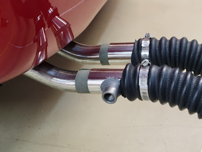
After determining that the fuel pumps were providing about 3 psi of pressure and the fuel lines and filters were clear, I started looking at the carburetors themselves. One problem was immediately obvious: while the accelerator pump's injectors on the rear carb were working well, the injector streams on the front carb were weak. Adjusting the linkage on the front pump had no visible effect. 


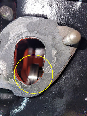
Original injector and ball valve.


While disassembling both pumps, cleaning them, and replacing the gaskets, I tackled the injectors and immediately hit a snag. During the disassembly process   the ball that serves as a check valve to prevent the gas already in the injector from draining back into the bowl popped out onto the floor and vanished as if teleported to a parallel universe. If this sounds like an excuse for not conducting a thorough search, try looking for a 3mm clear plastic, extremely bouncy, ball on the floor of a typical garage floor strewn with dust bunnies and other tiny debris. When you lose something on the floor that can't be seen or felt or picked up with a magnet, your last resort is to look for another one on the internet. 

Original injector (left) with new version.


Some material filing necessary!

Much to my surprise I found a site on eBay offering replacement injectors in a set of 4! When the jets arrived and I compared them with the originals, I discovered a number of minor differences: The blocks holding the injectors to the carb bodies were slightly longer than the originals but would fit after filing some material off the block. No big deal. The balls inside the lower part of the original injectors were removable, probably so the tubes could be cleaned, but the sealed one-way valves in the new design seem to be an improvement--at least it lessens the probability of losing the ball! Another difference is that the original injector orifices were 0.35mm, but the new ones are 0.40mm. Will that make a difference? I hope not, but we will soon see! 

The Solex Saga continues . . . .


Friday, February 4, 2022

What's in YOUR Junk Boxes? (Post # 166)

Exhaust ports are finally installed in the overhead door just in time for winter.

It's February 2nd and winter is making itself felt. Winters can be long up here in the mountains of northern New Mexico. This year is turning out to be relatively mild so far, but snow has been on the ground for the last several weeks and February is usually the coldest month. Over the years I have put a lot of effort into making The Shed a comfortable place to work no matter what the weather conditions, and that has paid off. Last week I completed a project that has been on the list for a long time but finally reached the top of the priority list: making it possible to run The Alfatross indoors by venting the exhaust through sealed ports in the overhead door. The project was made a little more complicated by the small diameter of The Alfatross' dual tailpipes.

Mating the exhaust hoses to The Alfatross' tailpipes.

The first task was to locate small diameter flexible exhaust hoses that could be mated to The Alfatross' tailpipes at one end and whatever I could cobble together at the door. When my on-line search for a "plug and play" solution was fruitless I turned to my junk boxes for inspiration and was immediately rewarded. 

Steel materials junk box.


Adapting tailpipe to exhaust hose.

The OD of The Alfatross' pipes is 42.34mm but the ID of the flexible hose, at 50.8mm, is too large, so I needed an adapter. My junk box for steel items coughed up a pair of short chrome exhaust tips exactly the right OD to fit the ID of the hose and almost exactly right to fit over The Alfatross' tailpipes. The junk box for gasket and seal materials  delivered 0.85mm strips of material that not only sealed the tiny gap between the tips and tailpipes, but also prevented the chrome tips from scratching the tailpipes.

The 4 piece PVC door penetration and cap.

At the door end of the exhaust hoses I needed something with an ID that would seal tightly with the hoses and an OD that would seal with the door--and mate with some kind of plug that would close it off when not in use. For this I turned to my PVC junk box and discovered that all my problems could be solved by cutting 60mm holes through the insulated door and sandwiching  lengths of 2" schedule 40 PVC pipe between 2" PVC couplings. The hoses fits snugly inside the interior couplings ID's and the exterior couplings hold the assemblies tightly in place. A cap with a wide flange seals them off when not in use.


Pleased with myself for figuring out how to solve this problem, I quickly bored holes in the insulated overhead door and installed the vents. When I operated the door I was relieved to see that the exterior PVC couplings cleared the top of the door opening . . . but dismayed when the door reversed itself because I mounted them in the path of the safety light beam! It was easy enough to correct by drilling new holes higher up on the door and making plates to cover the original holes, but what a rookie mistake!


LM-2 fuel/air sensor bung

 It wasn't long before I realized that I would not be able to use the LM-2 fuel/air analyzer's portable sensor with this arrangement and would have to modify one of the chrome pipe tips to install the sensor bung. Another easy fix, but I should have thought of that earlier too. 


I did not want to challenge my rudimentary welding skills by trying to mate the heavy iron bung onto the very thin steel tip, so I drilled a hole in the tip, ground a saddle shape into the end of the bung and secured it in place with JB Weld's Extreme Heat formula.

Interior aspect


Exterior aspect


Now, what's next on the priority list?  Oh yeah--back to work on the car: Solex carburetor tuning, Zagato family matters, addressing oil leaks, historical research, radiator overflow tank installation, road worthiness testing, concours participation, preparing for sale . . . .


Thursday, February 3, 2022

Slaying Dragons (Post #165)


Through no fault of its own, The Alfatross Blog has been sorely neglected over the last 6 months. No, Covid 19 is not the culprit. It was "Car Restorer’s Block". Every time I sat down to write another post I thought I really should be physically working on the car. Consequently, although work on The Alfatross herself has continued apace, reporting the problems and progress has not. Mea culpa.

Over the last year or more The Alfatross has confronted me with a series of dragons to slay: radiator leaks, exhaust system originality issues and insulation modifications, defective starters, erratic fuel pumps, carburetor jetting, instrument calibration—and that’s just the big ones. With 99% of the restoration behind us, the current problem is the engine’s refusal to transition from idle to load. 

FISPA mechanical fuel pump schematic.

In my last post back in June (Post #164) I was trying to solve what seemed to be a fuel supply problem. The Alfatross has two fuel pumps, an electric SU pump near the fuel tank and a FISPA mechanical pump operated by a cam on the crankshaft.  A toggle switch under the dash allows the driver to run the electric pump before starting the engine to make sure that the fuel line is full. It can be switched off as soon as the engine is running, leaving the mechanical pump to take care of normal running. A pivot axle in the FISPA mechanical fuel pump had worked its way loose, rendering the pump inoperable. The fix was successful, but the mechanical pump still could not supply sufficient fuel pressure to keep the engine running after starting.

Location of the mechanical fuel pump with lever arm on its cam.

I became suspicious that the original SU electrical fuel pump, restored about 12 years ago, might not be up to the task, so I removed, disassembled, and bench tested it, but could find no obvious problems. I went to the Moss Motors web site and discovered that SU still makes the same model pump, almost identical to the original. I ordered one and it arrived in less than a week!  So much for the difficulty of locating parts for 62 year-old imported cars!


The new SU pump from Moss Motors is virtually identical to the original (left).

The new SU pump produced just under 3 psi.

I managed to test the new pump’s pressure by patching a pressure gauge onto the mechanical pump’s outlet port and discovered that the electrical pump makes just under 3 psi, which should be sufficient to supply fuel even without the mechanical one. Then I tried turning over the engine with just the starter to run the mechanical pump by itself, but the needle on the pressure gauge never even twitched. I concluded that although the mechanical pump was not participating in supplying fuel under pressure, at least it wasn't impeding it. But why wasn't it working correctly?

Then I ran across a paragraph in the original Alfa 1900 Repair Manual (in Italian) stating the importance of coordinating the placement of the pump’s lever arm on the cam in order to obtain the maximum travel of the diaphragm and increased fuel supply.

Translation:"When manipulating the lever, it is advisable to bring the control eccentric of the pump in a suitable position, that is, with the lowest part in contact with the end of the lever 4, (referring to the drawing above) in order to obtain the maximum travel of the diaphragm and therefore a faster filling of the carburetor float bowl." 


Could that be why the mechanical pump isn't producing pressure? Is it even really necessary? There is no way you can see what position the cam is in because it is completely enclosed inside the engine block. But no matter what position the cam is in initially, with each revolution it moves the lever arm through its entire range—so what difference does it make? Let sleeping dragons lie.

OK. So maybe the Mechanical Fuel Pump Dragon wasn't actually slain, but at least he slunk back into his cave and I can move on. Now that I know the electric fuel pump is supplying sufficient pressure even without the mechanical pump, I can get on to examining and resetting the fuel metering elements of the carburetors, particularly the jets and accelerator pumps. 

The cam on the crankshaft that operates the mechanical fuel pump.
The cam that operates the pump seen through the pump port in the block.