The Alfatross

The Alfatross
The Alfatross in 1965 and 50 years later in 2016

Sunday, May 31, 2020

Convincing the Benzina Gauge and Sender to Work Together (Post # 153)


Preparing The Alfatross for her appearance at the Arizona Concours and the Santa Fe Concorso, we put only a few gallons of gas in the tank and didn’t worry much about how accurate the gauge was.  Now it was time to correct that. After filling the gas tank up completely for the first time I was disappointed to find that the gauge still read “0”. Because the Veglia BENZINA gauge was restored recently by Mo-Ma Engineering I figured the problem was more likely a faulty sender. With the sensor out of the tank, moving the cork float arm up and down produced erratic readings on my ohmmeter, so something was wrong inside. 
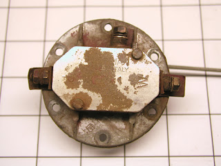
Top of the benzine gauge sender. Gauge
connects to W terminal, T connects to
warning 
light, third terminal is unused.
 
Bottom of sender with float rod.
A quick surf on the internet revealed that modern reproductions of the Veglia sender with more reliable solid-state electronics inside are available for purchase. But I had some reservations. That might be the easy way to solve the problem, but on the other hand maybe reproductions would not be calibrated to work with the original gauge--and those reproductions are expensive! 

Reproduction senders look very similar to the original.
Never having dissected a mechanical fuel level sender before, I saved the reproduction option as a last resort if the original was not salvageable. Opening the casing revealed that the components inside seemed to be in good condition in spite of their age. At the heart of the sender is a very Old School, very delicate, coiled wire rheostat attached at either end to terminal screws and curved copper blade contacts positioned above and parallel to the sides of the rheostat coil.  A fine wire from one end of the coil ran to a third terminal screw on one side of the case. Removing the terminal screws and rheostat coil revealed the grounding “brushes” mechanically attached at the bottom of the case to the float arm.

The rheostat coil, blade contacts, and terminals. Tips of
the brushes are out of sight.


The grounding brushes below the rheostat coil in the
"full tank" position
The sender performs two functions: monitoring the fuel level in the tank and illuminating a warning light inside the gauge when the level gets too low. As the float arm sinks, the brushes move along the sides of the rheostat, reducing resistance. The gauge translates resistance into movement of the needle from full to empty.  When one of the brushes makes contact with the copper blade near the end of its travel, it completes the light circuit at the third terminal screw. Turns out, this was the problem area.


The rheostat, a little discolored but otherwise completely functional.  The
insulated fine wire making the connection to the warning light was
shorting out on the casing, causing erratic readings.


After cleaning the contacts I bench-tested the sender with the gauge to make sure the old team agreed to work together again, and they did. 

Testing the cleaned up and reassembled sender  for compatibility with the gauge.  The problem was easy to fix-- 
but hard to pinpoint.  

So the BENZINA gauge is reliable now, but what about the ACUA and OLIO temperature and OLIO pressure gauges?  They're coming up next, and I have a feeling we're going to have problems with them, too. I have some spare senders for both oil and water, but what if there are problems with the gauges themselves?  We'll soon find out.


Monday, May 25, 2020

Little Gems of Ingenuity and Engineering (Post # 152)

One of  The Alfatross' Tudor windshield washer nozzles.
No sooner had the automobile been invented than everyone noticed it sure could use a transparent shield against the wind and rain: A "windshield"! It took a little longer to notice that the windshield needed a wiper. By 1913 they were largely standard equipment--rudimentary maybe, but functional. And it took even longer for someone to dream up the windshield washer.

Now, with wipers and washers that turn on and off by themselves, we take all that for granted. But in 1955 when The Alfatross was built, these things were relatively simple, technologically, but they still got the job done.


The original Tudor manual pump: no user serviceable
parts inside!

The original Tudor system, consisting of a plastic reservoir bottle and cap in the engine bay, three lengths of clear plastic hose in two different diameters, a miniature manual pump mounted in the dash, and two sprayers on the cowl, was intact, but the pump was DOA and could not be revived. I feel certain the system was original equipment because it could
The one-way valve included with the
reproduction Tudor manual pump:
two flimsy pieces of cheap plastic.
not be installed after the dashboard was in. The solution was to purchase a modern reproduction that also came with a reservoir bottle.
 When we were reassembling The Alfatross for its first concours event I paid little attention to its Tudor washer system, but now that I am working under the dash and making sure everything works and is roadworthy, I can take time to admire it. 
The original Tudor one-way valve: machined, threaded,
soldered, O-ring sealed, crimped, and still perfectly
serviceable!

The new system did not work. Push the button on the dash until the cows come home, but the windshield remained dry. I checked everything for leaks, took the pump out and tested it--everything worked fine outside the car, just not when reassembled in the car. I started looking at the one-way valve inside the new reservoir bottle that was supposed to prevent fluid from returning back to the bottle and draining the lines. It looked sketchy, just two pieces of imprecisely-made, poorly fitting plastic. Then I looked at the valve in the cap of the original bottle: two finely-machined bronze fittings with an O-ring between. The upper fitting contained a tiny stainless steel ball trapped in the tube serving as the one-way valve--simple, but fail safe!
A stainless steel ball inside the crimped end
of the top half of the valve acted as the
one-way valve. 


I threw the new, useless plastic valve out and replaced it with the old original and the pump worked perfectly--except now I had a leak in the tubing under the dash where it joined the sprayer on the passenger's side. This necessitated removing the sprayer and examining it closely. Like the bronze one-way valve for the reservoir bottle, each sprayer was a jewel of ingenuity and engineering: Three pieces of finely-machined bronze, two bronze washers, and a two-piece bronze hose connector made from two carefully mated tubes of different diameters. The problem was obvious: the hose connector had been broken in the past and poorly re-soldered. It was easily repaired with a touch of JB Weld epoxy and a little sanding.

The spray washers were dirty, but perfectly
functional. They are so hard to get to from
under the dash I started to think the rest
 of the car was built around them
.
The clever but simple design of the nozzles
themselves permits accurate aim and
variable output volume.

I threw the new, useless plastic valve out and replaced it with the old original and the pump worked perfectly--except now I had a leak in the tubing under the dash where it joined the sprayer on the passenger's side. This necessitated removing the sprayer and examining it closely. Like the bronze one-way valve for the reservoir bottle, each sprayer was a jewel of ingenuity and engineering: Three pieces of finely-machined bronze, two bronze washers, and a two-piece bronze hose connector made from two carefully mated tubes of different diameters. The problem was obvious: the hose connector had been broken in the past and poorly re-soldered. It was easily repaired with a touch of JB Weld epoxy and a little sanding. 

Maybe new is not always better than old. New is always fancier, but at least old is easier to repair. After all, how many modern "adaptive" wipers and washers with their solid-state microchip controllers will still be operational 65 years from now (in 2085)?

Wednesday, May 13, 2020

Snap! (Post # 151)


Snap!

The vent valve before restoration with cardboard "hood" taped on.
When it happened, I thought "no big deal" It's plastic.  I'll just glue it back together.  Little did I suspect how long it would take and what I would have to do to restore it. Because it was something that did not affect how The Alfatross ran or what it looked like--it was practically invisible, hidden away behind the glove box under the dash--I did not start to obsess on it until most of the "important" issues had already been addressed. 


The butterfly valve, control shaft, and broken paddle handle.

But when I did finally take a long hard look at it I realized that the "butterfly" valve controlling the flow of ventilation into the cabin on the passenger's side was probably a cylindrical prefabricated unit welded into the firewall as a single piece. The butterfly itself was made of a round rubber disk trapped between two stamped steel plates spot welded to a central shaft. The shaft was bent into an "S" shape at the bottom ending in a short paddle-shaped lever made out of what looked like black bakelite plastic. Notches in a steel plate welded to the bottom of the cylinder locked the butterfly in four preset positions ranging from completely open to completely closed.


I used the stump of the handle and the part that broke off to make a mold.  
That was the easy part!


You could take the nut and washer off the top of the butterfly shaft, but the butterfly was still trapped inside the vent pipe because it was spot welded to the shaft.

I got around that by grinding the spot welds down until I could pull the shaft out from the bottom--after marking the shaft orientation with respect to the butterfly angle! I knew I would have to make a mold of the handle but that was going to be a little tricky because part of it was still attached to the shaft and would have to be supported and aligned just right throughout the process.  


The clear Alumilite cast after drilling but before attaching it to the shaft. 


I used the wrong approach on my first attempt at casting a new handle. I thought I could keep the part of the handle that was still attached to the shaft and just replace the part that broke off, but the bond between the original material and the new cast was weak and broke again almost immediately. 


The finished and painted final assembly

On the next attempt I cast the entire handle using an epoxy resin called Alumilite. After removing the original bakelite part of the handle still attached to the shaft, I discovered that the shaft inside was cleverly flattened to resist twisting forces. I drilled a hole in the cast for the shaft, injected epoxy to lock it into place, and inserted the shaft at the correct angle.


The vent tube with butterfly valve secured with pins through the shaft.


Putting it all back together was pretty straight forward. I inserted the butterfly into the tube from the inside, ran the shaft through it, lined up the holes in the shaft with the ones in the butterfly, then inserted pins through the holes from the engine room to hold it in place.


A "foot's eye view" of the "re-manufactured" vent valve under the dash and behind the glove box.


Looking back on what I just wrote in a few minutes reminds me of how long it actually took, all the fiddling around to figure out how to do it, and all the wailing and gnashing of teeth when it didn't go as planned.  Maybe I should have started with a "Don't try this at home, folks!" warning.