The Alfatross

The Alfatross
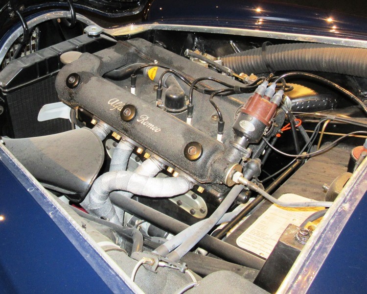
The Alfatross in 1965 and 50 years later in 2016

Saturday, April 28, 2018

Slip Slidin' Away (Post # 139)

Slip slidin' away,
Slip slidin' away.
You know the nearer your destination
The more you're slip slidin' away.


Left front wheel cylinder  and the offending
ball.
The two types of bleeder valves.  The shiny new
"improved" valve on the left and the old-fashioned ball
valve on the right.
The Alfatross' persistent brake problem continues to puzzle me even as I continue to try to trouble shoot it. I know! I know! It's a simple system with only so many things that can go wrong.  If I had a dime for every time a person helpfully suggested that perhaps all the fluid leaked out (without me noticing!), or maybe there is air in the lines, I could fly The Alfatross back to the Alfa factory in Italy and get them to do it!  

A few weeks ago  I was, under the car, working on the Alfatross' left front wheel cylinder. For some reason the bleeder wasn't acting right. When I opened it up to bleed the system (for what seemed like the tenth time!) I couldn't get a good flow, just an erratic dribble of fluid. I took the bleeder out and immediately saw that the pointed end was flattened and concave. What the . . . ?  I used a fine wire to probe the opening.  It seemed to be contacting some kind of obstruction but there was no way to look inside the bleeder opening. 

I did not really want to remove the whole wheel cylinder because that meant the wheel, hub, lug nuts, rondellas, drum, and shoes would have to come off too--a lot of work!  But I couldn't see any way around it.  


Normal bleeder on the left and the damaged bleeder
extracted from the left front wheel cylinder.  Note the
concave deformed tip caused by contact with the ball.
At that moment I realized that the SiriusXM radio was playing Paul Simon's song, Slip Slidin' Away, and I thought "Ain't that the truth"!  A year ago I thought I was coming down the home stretch with this restoration and now I feel like I'm farther away than ever!

I saw what the problem was as soon as I got the wheel cylinder off: a small steel ball was lodged in the bleeder opening.  The original 1955 vintage bleeders on The Alfatross' wheel cylinders used a steel ball to seal the opening.  The bleeder screw had a flat nose with a shallow concavity to keep the ball centered.  We switched over to the new, supposedly better-sealing bleeders with pointed ends during the restoration, but somehow this one steel ball was not removed.

So does the story have a happy ending?  No, I'm still slip slidin' away! This simple repair did nothing to ameliorate the overall brake problem (more about that in the next posts), but I am glad it was found and fixed.  And yes, I did do a thorough check of the other three bleeders, all of which were in proper order. 


Monday, April 16, 2018

There's More Than One Way to Skin a Cap (Post # 138)

The basic Motive Products pressure tank
and feeder hose.  It can do a lot of other
jobs too, like fill your transmission.

If you can't get your brake system to bleed the normal way by pumping the pedal, maybe you can pressurize the reservoir and "force bleed" it.  This is the whole premise behind a variety of kits  made by Motive Products https://www.motiveproducts.com/products/0100-european-bleeder. Sounded good to me. Nothing else I tried worked, so what have I got to lose?  I also liked the idea that theoretically you could bleed your brake system by yourself.  Theoretically.

The idea is simple, and so is the equipment: a Nalgene pressure tank with a gauge that can be pumped up to 30 psi (more pressure than you need to do the job), a few feet of clear plastic tubing, and a variety of caps to fit various types of reservoirs.They even make a kit that includes a cap for "European vehicles with a 45 mm opening".  Because the Girling tank opening measures 44.5 mm I thought maybe that's close enough.

The first problem was this breather nipple on
the underside of the cap.  A few drops of 
lacquer thinner dissolved the adhesive  and it
came loose by itself.
So I ordered one.  I did not really expect any of the supplied caps to fit The Alfatross' 1950s vintage Girling reservoir, so I was not disappointed when they didn't.  The only question was what would it take to make it work?  Could the Girling cap be modified to take the feeder hose and be leak proof?  Only one way to find out! Fortunately, I had a spare Girling reservoir I could experiment with.  It turned out to be pretty easy to adapt the Girling cap to the basic Motive Products kit. The hardest part was patiently waiting for the adhesive to set.

As I write this, the cap is on the reservoir in the car and I have pressurized it. The pressure tank's volume is 2 liters, which is way more volume than the brake system needs.  It would have been helpful if the manufacturer had mentioned that even with 5 bottles of fluid in the tank it takes about 150 strokes to get the pressure up to 15 psi! 

The "power bleeder" does work and it can be done single-handed, but through no fault of its own, it did not cure the problem(s) The Alfatross is having.  More about that in the next post(s).

Now, with the nipple out of the way I could
drill through the cap from the inside and screw
on this nylon hose barb fitting.  

A generous amount of my favorite all-purpose
adhesive, E-6000, made it an airtight seal.


At this point the cap was reunited with the
reservoir and pressure tested before being
filled with brake fluid.
The center of the original rubber cap seal had
to be removed to accommodate the end of the
hose barb.


The right-angle hose barb seemed like a good
idea at the time because there is very little

clearance between the top of the cap and the
body, but it made removing and reinstalling
 the cap very clumsy.  Of course this cap is  just
 for "power bleeding".  The original goes back 
on for normal service.


Sunday, April 8, 2018

For Questions About Originality, Ask Italy! (Post #137)

Gigi's photo of an original aluminum master cylinder cover
(copertura) in place.  Luigi Ventura.
Original copertura (right) and its
 reproduction.  Paolo Galafassi.

As mentioned in the last post, Gigi Ventura made me aware that his friend Paolo Galafassi (https://www.classicvintagecar.it/) has not only rare original examples of the heat shield over the first muffler set, but also the "copertura" covering the master cylinder.  I have to admit I was at first skeptical that such a feature was an original factory item because although I have seen the underside of quite a few 1900s, none of them was equipped with one.  Furthermore, no such cover for the master cylinder appears in the official Alfa parts catalog for 1900s.  The first photo Gigi sent did nothing to convince me.  It showed a somewhat battered-looking alloy box, open at the top and back, covering the area around the master cylinder. Then I noticed in the same image the unusual finned oil pan sump, oil filter housing, and the front suspension lowering spacers.  Hmmmm--maybe the copertura was a modification too?
The factory-installed screw holes in the Alfatross' chassis
for attaching the master cylinder copertura.
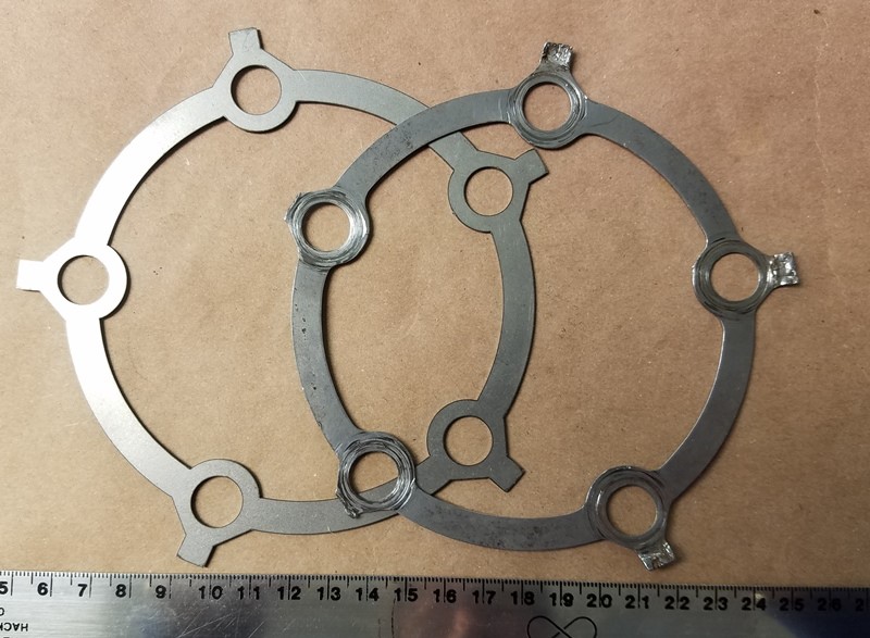
One of The Alfatross' original rondellas (right)
and Paolo's reproduction (left).
I wrote back to to Gigi to express my skepticism. In reply, he sent photos of an original surviving copertura alongside a reproduction made by Paolo's shop.  But the thing that really convinced me that coperturas were original factory equipment was the four attachment points Gigi told me to look for on The Alfatross' chassis.  Sure enough, there they were, and not just holes drilled for sheet metal fasteners, but carefully made threaded inserts for 5mm x .80 machine screws!

I immediately put in an order with Paolo for reproductions of both the exhaust heat shield and the copertura.  On the same page of Paolo's Web site  https://www.classicvintagecar.it/catalogo/ricambi/alfa-romeo/1900/freni-1900/, I also saw something else I had been looking for: rondellas--the steel rings that securely lock the lug nuts to the splined wire wheel hubs. 

Paolo's reproduction copertura fit The Alfatross perfectly.
It will be painted black to match the chassis color.
Note the 3 fasteners along the longitudinal
frame member and 1 on the transverse
member.
Having had some bad experiences during The Alfatross' restoration when ordering reproduction parts, I am delighted to report that all three orders arrived quickly, were carefully packed, and just as advertised--and the prices were very reasonable.  Grazie Gigi and Paolo! It doesn't get any better than that . . . .


Monday, February 26, 2018

The Last Detail . . . (Post # 136)

Master welder Chris Felix carefully makes the 10 TIG
welds mating the exhaust sections and hanger tabs
together. 


The exhaust system is finally finished--welded, aligned, scuffed, painted, polished, and insulated.  Finished, but not installed yet.  
I decided to insulate the top of the last set of  mufflers with
"lava shield", a thin sheet of material made from crushed
volcanic rock, in order to protect the Zagato paint and
body work inside the confined space in the rear muffler
recess.

There are a couple of reasons for this. The main one is because I need to complete work on the brake system first, and that is more easily done while the exhaust is out of the way.  But, in the form of a comment from Gigi (Luigi Ventura) affter the last post, another reason presented itself: the opportunity to add a rare element of both improved functionality and authenticity!    

Gigi informed me that he knew someone who actually had more than one original example of the coperatura (heat shield) Alfa originally fitted on top of the first set of mufflers on 1900 SS models--and that he was willing to make a reproduction for The Alfatross! I knew these heat shields existed because they are illustrated in the Alfa parts catalog for the 1900 SS model, but The Alfatross did not have one when I got it in 1969 and I had never seen one on an actual vehicle.  I assumed they were the automotive equivalent of a unicorn's horn. But thanks to Gigi, and in keeping with my intention to restore The Alfatross as faithfully as possible, we ordered one!

Gigi's friend, Paolo Galafassi, has a shop specializing in classic Alfas  https://www.classicvintagecar.it/ If you have an Alfa 1900, you need to know about Paolo and the services he can provide. He has a lot of original parts and also makes reproductions to a very high standard, all at very reasonable cost.  While I was putting together my order for the exhaust heat shield and a shield for the brake master cylinder (more about that in the next post), I also added 4 "rondellas", the "lock washers" for the lug nuts holding the brake drums to the wheels. The Alfatross' originals have seen a lot of use!
The finished Quicksilver exhaust system.


The insulating aluminum cover (yellow circle)
over the first pair of mufflers is clearly
illustrated in this drawing from the Alfa
Romeo  1900 parts catalog.  Easy to find the
picture, very hard to find the part!


Examples of original heat shields attached directly above the first muffler set on a 1900 SS
chassis.  The function and location of the heat shield put it squarely in harm's way and most
did not survive into the present day.  Paolo Galafassi, Classic Vintage Car. 
https://www.classicvintagecar.it/chi-siamo/
Paolo Galafassi's reproduction muffler heat shield 
compared with a well-used original.  
https://www.classicvintagecar.it/


All the parts were in my hands less than a month after placing the order and the whole process could not have been more satisfactory. So now the exhaust system is ready for installation.  None of the 1900 SSZ Alfas I have seen in person have this heat shield, but at least some owners have complained about excessive heat coming from the floorboards.  Perhaps the heat shield is an essential part of the exhaust system, not just a garnish. We will know soon enough, but I still have to solve the brake problem before it can all go back together.


Saturday, November 25, 2017

Hotfooting It (Post # 135)


Wrapped headers on chassis *01909*.
 The Heatshield Products exhaust armor's
inner ceramic fibers layer is capable of
withstanding 1800 degrees F continuously.
Now we're back to the exhaust system, following Post # 129. The Alfatross has a hot engine. No, really, I mean HOT! And the exhaust gasses are the hottest part.  Alfa engineers knew this, so 1308 SS engines came from the factory with aluminum and asbestos heat shields protecting the starter, generator, and part of the steering column from the intense heat radiating off the headers.  A dedicated aluminum scoop and shroud ventilated the entire exhaust side of the engine when in motion, but was of little help otherwise. We need to get those hot gasses away from the car as fast as possible while at the same time keeping the decibels down to a civilized level. Alfa engineers put the first of three pairs of mufflers or resonators right under the driver's seat. At this point in the system the gasses are still at a few hundred degrees F. This might seem like a dumb thing to do, but if you look around under the chassis there really isn't any other place to put it, given that the chassis is short and you still need to find space for two more muffler pairs. 
The corrugated metallic outer layer keeps the
inner layer together and allows it to be shaped.

We discovered this "engineering compromise" during the 2016 Arizona Concours d'Elegance. Positioning the cars on the field in the wee hours took a long time, with a lot of stopping, idling, and waiting.  Even though the pre-dawn January morning was quite chilly the cabin became uncomfortably warm very quickly.  Fellow 1900C SSZ owner David Smith experienced the same phenomenon while preparing his car (*01947*) for Pebble Beach this year. During road testing the floorboard got so hot it started to melt his shoes! The only viable solution is to add more insulation between the first pair of mufflers and the floor under the driver's seat.


The Heatshield Products "Exhaust Armor" installed on 
top of the insulation previously fixed to the bellypan creates 
a good two cm total insulation between the exhaust system
 and the floorboard directly under the driver's seat. 
The third muffler pair hides in a recess in
the bodywork with no more than half an 

inch of clearance on either side.  

Trial fitting the Quicksilver exhaust system in preparation for tack-welding.  Altogether there are 10 joins, 2 hanger tabs, and a brace to weld.

Now that The Alfatross' new Quicksilver exhaust system is welded up and almost ready for installation, it's time to beef up the insulation in a discreet manner that does not detract from its originality. There is no question that insulation materials and technology available today do their job quite well, and some 1900 owners have gone so far as to wrap their headers, but some authorities think this practice may be damaging to the headers themselves. In any case use of header wrap for The Alfatross would be an inappropriate anachronism. On the other hand, replacing the traditional asbestos insulation attached to the bellypan beneath the driver's seat with modern materials is easy to do and should make a big difference without even being visible. 

Another place where the exhaust system could stand additional insulation to keep it from damaging the body paint is the muffler recess in the trunk area where the last pair of mufflers reside. On Zagato bodied SS cars like The Alfatross this space is only about 7 inches wide, leaving about half an inch of space on either side of the twin mufflers--too close for comfort!  


The Lava Shield mat material looks like carbon fiber and
is only 0.008 thick, but is said to reduce radiant heat by up
to 80%.  

After some online research I ordered two different kinds of insulation for the two applications, both manufactured by Heatshield Products (https://www.heatshieldproducts.com/): "Exhaust Armor" for the area under the driver's seat and "Lava Shield" for the last pair of mufflers in the recess. "Exhaust Armor" is a mostly fibrous ceramic material 0.50 inch thick bonded to a dimpled metallic sheet said to be able to resist 1,800 degrees F continuously, while reducing radiant heat by 60%. "Lava Shield" is a completely different material ("made of crushed volcanic rock" according to the manufacturer).  It comes in the form of a self-adhesive mat only 0.008 inch thick but capable of reducing radiant heat by 80%.

At this writing the Quicksilver exhaust system is back on the workbench following a test fitting to make sure everything is still in alignment after welding. The next step is prepping it for coating with the same high-temperature flat black paint I used on the first system.  I won't know how effective the heat shields are until after the whole system is back on and the engine fired up. One thing I can say for sure is this better be the last time anything having to do with the exhaust system needs attention--I'm tired of living under a car!


Thursday, October 19, 2017

What Does The Alfatross Have in Common with Washington DC? (Post # 134)


The Alfatross is marking its territory.  How do you
determine the severity of a leak from its puddles?

They both have leaks!  


Engine oil leak fluorescing under ultraviolet light showing that the 
leak is between the pan and the sump.
The Alfatross has several circulatory systems for its various fluids: coolant that circulates between the radiator, engine, and heater; oil circulating throughout the engine from the oil pan to the oil pump to the cylinder heads, camshafts, crankshaft, and piston rings; fuel that has to move from the gas tank to the electric fuel pump to the mechanical fuel pump to the carburetors; brake fluid that moves from the reservoir to the master cylinder to the wheel cylinders and part way back; steering gear fluid inside the steering box; hypoid gear oil inside the differential; and even another type of oil splashing around inside the transmission.  

It seems that all those different fluids just can't wait to escape and are looking for opportunities at every turn. It isn't easy to keep them in captivity. Because they are relentlessly stored, released, heated, cooled, compressed, decompressed and recycled while doing their jobs, they have to pass through tubes, chambers, reservoirs, pumps, valves, and sumps made from different materials with different expansion and contraction coefficients--all grudgingly held together with different types of seals and gaskets.  It's not an easy life.
Minor leak from a crack at the engine oil temperature port
in the back of the sump.

We tend to forget this because automotive engineers have virtually eliminated engine oil leaks in modern cars, but things were different when The Alfatross was born 62 years ago.  Oil and fluid leaks were more or less expected and not cause for alarm.  I was reminded of this recently during correspondence with members of the "Alfa 1900 Brain Trust".  After determining that The Alfatross has an engine oil leak somewhere between the pressed steel oil pan and the sump, as well as a crack just below the oil temperature sensor port in the sump, I sent out a plaintive query asking what could be done to fix them short of pulling the engine.  The responses were as bleak as they were historically enlightening:

Joost Gompels (gallows humor): My car leaked oil. I thought it was the oil temp sensor at the back of the oil pan and the gear box from a bad shaft seal as it got less as the oil level fell. Possibly hairline cracks in the casing.  I found it hard to seal the cam rocker covers because of the locator pins, warpage and overtightening. Thought we all subscribed to the wisecrack that if an Alfa did not leak--it had run out of oil! 

Peter Marshall (look on the bright side): I duuno!  I always thought that the Austin 7 survived well because the chassis accumulated a little oil rather than rust. I have never looked that hard at whether 1900s drip much. 

Giuseppe Maranghi (careful how you treat it!): As all pre-Fiat Alfas have a generous oil pump, both in pressure and quantity, NEVER run at hi revs a cold Alfa engine, otherwise the cold oil, supported by the generous pressure, will find by itself more than one way to "escape" out of the block. Did You all know that Motorway Police Giulia SW had a sort of heating plugs, like those for diesel engines, to keep the engine properly warmed in case of emergency? 
Dan Allen (just cowboy up and fix it!): Steel is more susceptible to vibration cracks especially around fittings and seams. I think anyway.  Also Don, it is very unlikely the engineers design an engine with thought of future R&R [in response to my observation that you can't remove the oil pan and sump without removing the engine].  Generally Alfa liked to put the engine and trans together for installation and most likely would recommend the same if they needed to come out. [meaning that I would have to remove both the engine and the transmission just to seal a leak in the oil pan!]
Joost (Oh those pesky Russians!): One cannot generalize too well. There are many different types of steel and alum alloys. Take an aircraft and a bridge for example. One is aluminum and the other steel almost exclusively yet both flex and vibrate in service not to mention expansion and contraction. Giuseppe may wish to comment on this that Italy after WWII had to import low quality Russian steel while able to manufacture aluminum itself. So it's choice of materials might be governed by other factors. Basically aluminum is a better heat conductor and its bigger mass and the ability to easily cast fins on its outer surfaces lets it dissipate heat from the oil pan better than a steel one.  
Giuseppe ("Stalin", in Russian, means "made with steel"): Well, it's not a comment, it's History, but nobody will find it in Italian books:  When Fiat decided for a joint-venture with Stalin "and company", the payback was not Russian "rubles", but full-of-sulphur (and maybe something else!) Russian steel, hence those 127s, 131s, Lancia Betas, Alfettas, Alfa6s and, above all, Alfasuds, carved like Swiss cheese. Italy, having the biggest communist party in the western block, even supporting Red Brigades, and all big factories in need of steel--Alfa Romeo  included--had to buy Russian one, just to keep the political situation quiet.


Leaks--how much is too much?

  
5 ml of engine oil isn't much!
By modern standards, any leak is too much.  By 1955 standards a small leak is nothing to be concerned about, but at what point should you start to worry?  One slow afternoon I did an admittedly sketchy experiment to figure out how much engine oil The Alfatross is losing over time. Because the drops from the leaks were landing in different places under the car I could not easily measure the volume of leakage, but I could measure the size of the puddles and compare them with surrogate puddles made from precise amounts of oil created elsewhere on the shop floor.  I filled a syringe with 1, 2, and 5 ml amounts of the same kind of oil in the crankcase, squirted them on the floor,  then waited a couple of days to see how much area they spread out to cover.  To my surprise, the three samples spread out and joined up to create a puddle about 9 inches (23 cm) across.  I estimated a puddle that size would represent at least a couple of week's worth of leakage. If The Alfatross' crankcase holds about 8 quarts of oil and there are 946.353 ml in a quart, there are 7,570 ml of oil in a full crankcase.  Assuming a steady rate of leakage of 0.57 ml/day it would take about 1,887.6 weeks, or about 36.3 years to drain the crankcase!


Individual puddles created by 5, 2 and 1 ml
"drips" before spreading out.  Scale is in
cm.
The puddles spread out to form a single
puddle estimated at about 9 inches or 23 cm
across.  Roughly 2 weeks worth of leakage.


So call me obsessive, but that's too much!


Tuesday, September 19, 2017

Small Change Saves Big Bills (Post #133)


This exploded diagram of a 1900 Alfa's rear suspension from the official Alfa Model 1900 Parts Catalog solved a mystery, saved me a lot of trouble, and once again proved that you cannot take too many photos or make too many sketches when you are in the disassembly phase.

I took The Alfatross' rear suspension apart about 25 years ago when I still had not learned that lesson. I bagged all the parts and labeled them but--digital photography being at that time not even a glimmer in anyone's eye--did not have the means to photograph everything in its original location on the car.

When I reassembled the rear suspension about 18 months ago I re-used almost all the original cleaned and restored parts except for the drop stop straps.  The originals were made of some kind of fibrous material that was worn, frayed, tattered, and unsafe so I replaced them with widely available new reproductions that come with neatly cut holes ready to install. 

All I had to do was bolt the straps to the chassis under the big rubber bump stops, wrap them around the axle, and connect the ends. Among the rear suspension parts I had two small steel plates with holes matching the spacing on the straps, but mistakenly assumed [Mistake No. 1: don't assume anything.  Spend the time necessary to think it through.] that the straps were supposed to be secured end-to-end, which would mean that I was really supposed to have four little plates, not just two [Mistake No. 2: The more assumptions you have to make, the more unlikely an explanation is.] So I cut and drilled two steel attachment pieces, each with four holes to fill that function--and thought I was being very resourceful.


The "over-improved" drop stops utilizing
fabricated plates to connect the strap end-
to-end instead of overlapping. The result of
a failure to apply Occam's Razor.


The drop stop clamp plates.  Note the distinctive
ridges along the edges.


The Parts Catalog drawing of the drop stop shows clearly
that the strap ends overlap each other and (not so  clearly)
that they are secured with  two sets of bolts, washers, and
nuts passing through the holes in the straps and clamp

(no. 29). 
While replacing the rear suspension springs in order to lower the ride height I had occasion to look at the exploded diagram in the Parts Catalog again. This time, I noticed the small window in the upper right corner showing all the parts for both the drop- and bump-stops and finally realized that I had the right parts all along, I just wasn't putting them together right!  Not only that, I went to a lot of unnecessary trouble to do it all wrong!

Correcting this seemingly small mistake shortens the strap length and reduces the distance the rear axle can move downward by more than an inch. I am sure the Alfa engineers who designed the suspension system set the drop stop distance where it is for a reason, and allowing the rear axle to move an inch or more downward could cause damage to other components under certain circumstances, so I am relieved to correct this mistake in time.  It also means that the exhaust system can be attached an inch closer to the chassis. 


Correct attachment with strap ends overlapping and held together
with 10 mm bolts passing through the steel clamp plate, straps, washers, and
secured with nuts. 

So now, having removed or detached, replaced or reconnected the fuel pump, fuel lines, brake lines, emergency brake lines, axle supports, drive shaft, rear springs and drop stops in order to get the ride height sorted out . . . I can finally get back to where I was a month ago: attaching the new exhaust system.