Over the last year or more The Alfatross has confronted me with a series of dragons to slay: radiator leaks, exhaust system originality issues and insulation modifications, defective starters, erratic fuel pumps, carburetor jetting, instrument calibration—and that’s just the big ones. With 99% of the restoration behind us, the current problem is the engine’s refusal to transition from idle to load.
 |
| FISPA mechanical fuel pump schematic. |
In my last post back in June (Post #164) I was trying to
solve what seemed to be a fuel supply problem. The Alfatross has two fuel
pumps, an electric SU pump near the fuel tank and a FISPA mechanical pump
operated by a cam on the crankshaft. A toggle
switch under the dash allows the driver to run the electric pump before
starting the engine to make sure that the fuel line is full. It can be switched
off as soon as the engine is running, leaving the mechanical pump to take care
of normal running. A pivot axle in the FISPA
mechanical fuel pump had worked its way loose, rendering the pump inoperable.
The fix was successful, but the mechanical pump still could not supply
sufficient fuel pressure to keep the engine running after starting.
 |
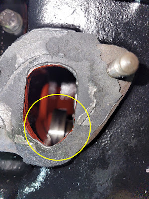
| Location of the mechanical fuel pump with lever arm on its cam. |
I became suspicious that the original SU electrical fuel pump, restored about 12 years ago, might not be up to the task, so I removed, disassembled, and bench tested it, but could find no obvious problems. I went to the Moss Motors web site and discovered that SU still makes the same model pump, almost identical to the original. I ordered one and it arrived in less than a week! So much for the difficulty of locating parts for 62 year-old imported cars!
 |
| The new SU pump from Moss Motors is virtually identical to the original (left). |
 |
| The new SU pump produced just under 3 psi. |
I managed to test the new pump’s pressure by patching a pressure gauge onto the mechanical pump’s outlet port and discovered that the electrical pump makes just under 3 psi, which should be sufficient to supply fuel even without the mechanical one. Then I tried turning over the engine with just the starter to run the mechanical pump by itself, but the needle on the pressure gauge never even twitched. I concluded that although the mechanical pump was not participating in supplying fuel under pressure, at least it wasn't impeding it. But why wasn't it working correctly?
Then I ran across a paragraph in the original Alfa 1900 Repair Manual (in Italian) stating the importance of coordinating the placement of the pump’s lever arm on the cam in order to obtain the maximum travel of the diaphragm and increased fuel supply.
Translation:"When manipulating the lever, it is advisable to bring the control eccentric of the pump in a suitable position, that is, with the lowest part in contact with the end of the lever 4, (referring to the drawing above) in order to obtain the maximum travel of the diaphragm and therefore a faster filling of the carburetor float bowl."
Could that be why the mechanical pump isn't producing pressure? Is it even really necessary? There is no way you can see what position the cam is in because it is completely enclosed inside the engine block. But no matter what position the cam is in initially, with each revolution it moves the lever arm through its entire range—so what difference does it make? Let sleeping dragons lie.
OK. So maybe the
Mechanical Fuel Pump Dragon wasn't actually slain, but at least he slunk
back into his cave and I can move on. Now that I know the electric fuel pump is supplying
sufficient pressure even without the mechanical pump, I can get on to examining
and resetting the fuel metering elements of the carburetors, particularly the jets
and accelerator pumps. The cam that operates the pump seen through the pump port in the block.